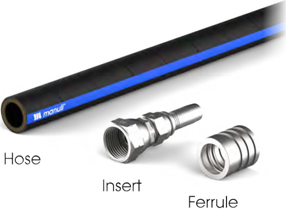
Hydraulic Style Hose
Assembly Instructions
Guidance for hydraulic hose assembly
Hose assembly drawings should report the following components of the final assembly:
- Hose Specifications
- End Fitting A
- End Fitting B
- Accessories
Note: Re-ending of hoses can lead to premature failure and safety hazards, including equipment damage, fire risk and environmental pollution.
Recommended practice from International Standards:
- ISO 4413 – Hydraulic Fluid Power – General rules and safety requirements for systems and their components
- ISO 17165-2 – Hydraulic Fluid Power – Hose assemblies – Part 2: Practices for hydraulic hose assemblies
- ISO 1402 – Rubber and Plastics Hoses and Hose Assemblies – Hydrostatic testing
- SAE J1273 – Recommended Practices for Hydraulic Hose Assemblies
- SAE J343 – Test and Test Procedures for SAE 100R Series Hydraulic Hose and Hose Assemblies
Safety & Competence
Competence to Assemble Hoses
All persons involved in hose assembly procedures must be competent and have undergone suitable training in the proper use of the equipment, materials, assembly procedures and testing by a qualified Manuli Hydraulics trainer.
The competence of all hose assembly staff should be regularly assessed and the results recorded on file.
Note: Where applicable, type approved (TA) hose assemblies (such as DNV; ABS; LR;BV, etc.) shall only be assembled by certified assemblers according to related specific rules.
Safety Procedures
- Wear suitable Personal Protective Equipment (eg: eye protection, hearing protection etc.) when necessary
- Ensure adequate ventilation and light when working
- Do not wear loose-fitting clothing, neck-ties and rings when operating moving or rotating equipment, and ensure long hair is tied back
- Do not mix and match assembly components from different manufacturers
- Do not reuse fittings unless reuse is specifically authorised by the manufacturer
Note: The above is not an exhaustive list of safety precautions, and good workshop practice should always be observed.
Component selection
Select the hose, inserts and ferrules according to the specification document for the hose assembly.
1st
1. Cutting the Hose
1.1 Tools required
Hydraulic hose should be cut using an appropriately sized cutting machine fitted with one of the following blade types to minimise heat damage to the rubber:
Suitable for cutting hoses of all types with preference towards small and medium sizes.
Available in sizes:
- Ø254mm
- Ø300mm
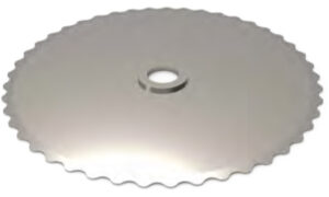
Scalloped Blade
Ideal for cutting hoses of all types and sizes. Provides the longest service life and the highest quality of cut.
Available in sizes:
- Ø400mm
- Ø520mm
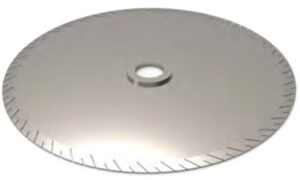
Micro-Slotted Blade
1.2 Assembly Length
According to international specs (e.g. SAE J517), there are two critical lengths referred to a hose assembly:
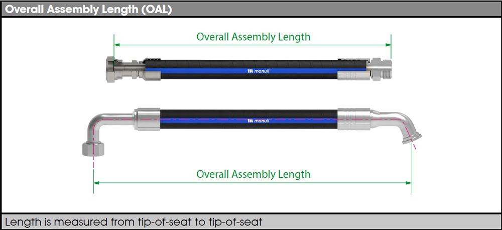
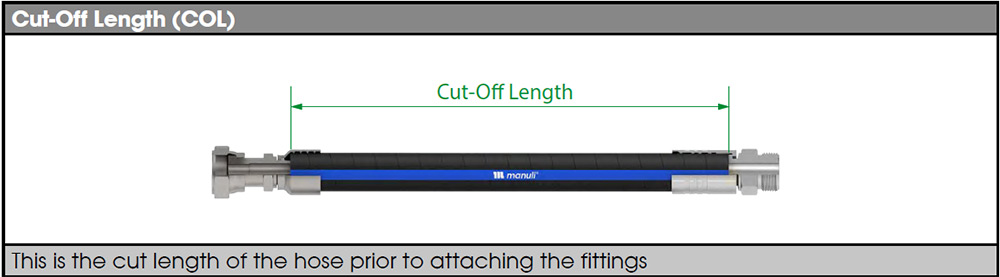
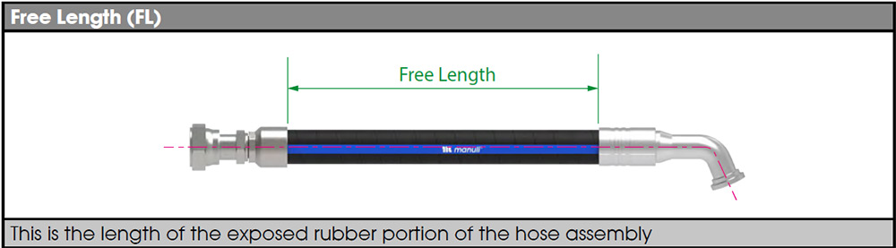
For hose installation and flexibility purposes, there is also a third relevant length known as the “free length”.
For assembly purposes, the Cut-Off Length is necessary, its calculation is made subtracting the two “A” (fittings Cut-Off values) from the Overall Assembly Length.

It is important to consider international norms tolerances for deviation of length of assemblies against what is specified.
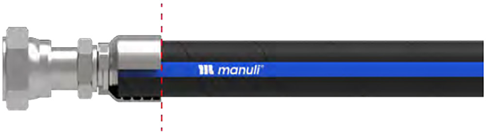
1.3 Cutting Angle
Cut the hose squarely (cut angle must be less than 2°) using an appropriate blade to minimise heat damage to the rubber.

1.4 Cutting Technique
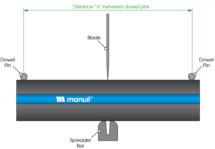
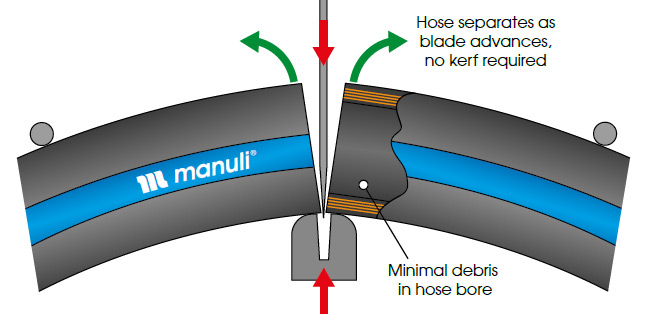
This minimises the contact between the cut ends of the hose and the sides of the blade, producing less heat and kerf deposits for a cleaner, safer cut.
Note: After cutting it is possible that there may be some wires from the reinforcement protruding from the cut end of the hose. Use suitable tools to cut or grind the wires away in order to allow safe handling of the hose during the next steps.
2. Cleaning the Hose Bore
Once the hose has been cut there will be rubber and reinforcement particles or cutting grit inside the hose bore, which must be removed.
An appropriate method of cleaning should be chosen depending on the intended application of the hose assembly, or the customer’s specifications for cleaning.
It is recommended to use proprietary cleaning pellets propelled through the hose with compressed air.
Hose bore shall be inspected to ensure the cleaning pellet has exited the hose.
WARNING:
Failure to remove debris from the hose prior to use can result in contamination of the entire hydraulic system on which the hose is later used. This can damage components and reduce the service life of the system.
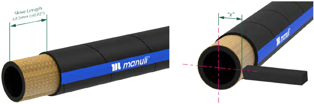
3. Skiving the Hose
3.1 – Tools required
External skiving of hoses can be carried out using a number of tools and methods, including the use of:
- Hand tools
- Wire and abrasive wheels
- Specialised skiving equipment (see Manuli Hydraulics Assembly Equipment Catalogue)
Note: The use of specialised skiving equipment is highly recommended.
Note: Internal skiving requires the use of dedicated, specialised skiving equipment.
3.2 – Skiving procedure
Using hand tools (external skive only)
- Clamp the hose securely in a vice or other suitable holding device.
Note: Ensure that the hose is not crushed or otherwise damaged by the clamping action.
- Mark the correct skive length around the circumference on the outer cover of the hose.
- Cut through the outer cover and down to the reinforcement around the circumference of the hose at the marked length.
- Starting at the circumference cut, use a blade or other suitable tool to remove the rubber in the section to be skived down to the reinforcement.
Using a wire or other abrasive wheel (external skive only)
- If the wire / abrasive wheel machine is bench-mounted, ensure that it is securely fixed to the surface and cannot move during use.
- If the wire / abrasive wheel machine is hand-held, clamp the hose securely in a vice or other suitable holding device.
Note: Ensure that the hose is not crushed or otherwise damaged by the clamping action.
- Mark the correct skive length around the circumference on the outer cover of the hose.
- Switch on the wire / abrasive wheel and grind away the cover in the skive section until the reinforcement is visible.
Using specialised skiving equipment (internal & external skive)
Note: Each skiving machine is different and has its own method of operation which should be followed. However the following steps should be observed where appropriate.
- Select the correct mandrel and skiving tool for the hose size required.
Note: Ensure the knife of the skiving tool is sharp.
WARNING:
Dull tools will not remove material as effectively as sharp tools, and can result in ragged or uneven skiving. They will also require more pressure to perform a cut, which increases the risk of injury to the operator.
- Insert the mandrel and skiving tool according to the equipment manufacturer’s instructions.
- Set the skiving length so that the front edge of the skiving knife is set to the correct length to within ±0.5mm (±0.02”).
- Set the skiving knife to the appropriate radius “x”, which will remove the maximum amount of rubber without damaging or displacing the reinforcement.
- Lubricate the mandrel and, if necessary, the internal surface of the hose.
- Start the skiving machine.
Note: When skiving Manuli wire spiral hoses, the direction of rotation of the tool should be anti-clockwise for external skiving, and clockwise for internal skiving.
- Carefully align the hose with the mandrel.
- Apply steady pressure to slide the hose onto the mandrel until it hits the stop on the mandrel.
- Withdraw the hose from the mandrel whilst the skiving machine is running.
Note: It may be necessary to make several passes to achieve complete removal of the rubber from the skived area.
IMPORTANT
Incorrect skiving length can result in deficient hose-fitting attachment and reduced service life of the hose assembly.
| Skive Type | Too Short | Too Long |
| External | Ferrule may not grip the hose correctly | Ferule may not produce an effective weather seal |
| Internal | The insert may not be able to be fully inserted | The insert may not locate or seal correctly |
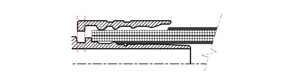
4. Insertion of Fittings in the Hose
4.1 – Two-Piece Fittings

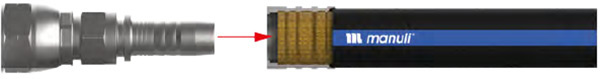
No-Skive type ferrule: ensure the hose is butted up to the stop-collar, push the insert up to contacting the hose, ensure the insert latch and ferrule collar are lined up correctly prior to crimping.

Skive type ferrule: position the ferrule on top of the skived area, push the insert up to contacting the hose, ensure the insert latch and ferrule collar are lined up correctly prior to crimping.
4.2 – One-Piece Fittings
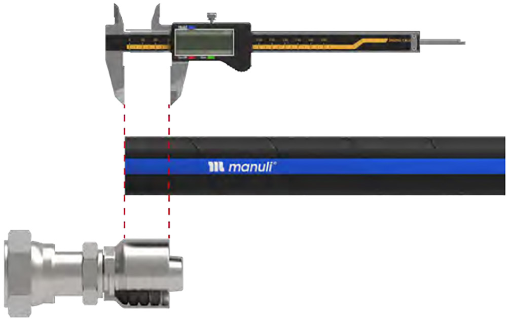
2. Push the fitting onto the hose until the open end is level with the mark on the hose. Note: Large-bore fittings may require the use of a pushing machine.
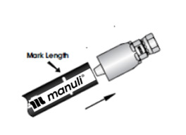
Mark Length for Non Skive Hoses.
When inserting crimp couplings into the hose bore, it is necessary to ensure that the hose tail insert is pushed fully into the hose. This is not visible by an external inspection of non-skive hose.
Prior to inserting the coupling, a mark is made on the cover of the hose, refer below. The coupling must be pushed into the hose until the edge of the ferrule is in line with the mark to ensure full insertion has been achieved.
The mark length also allows for inspection after the ferrule is crimped to ensure that the coupling has remained fully inserted onto the hose during the crimping operation.
Obtain mark lengths from the latest version of the MH crimp tool available on the web and APP, at following web site: www.manuli-hydraulics.com and log into the Manuli Crimping Data Tool.
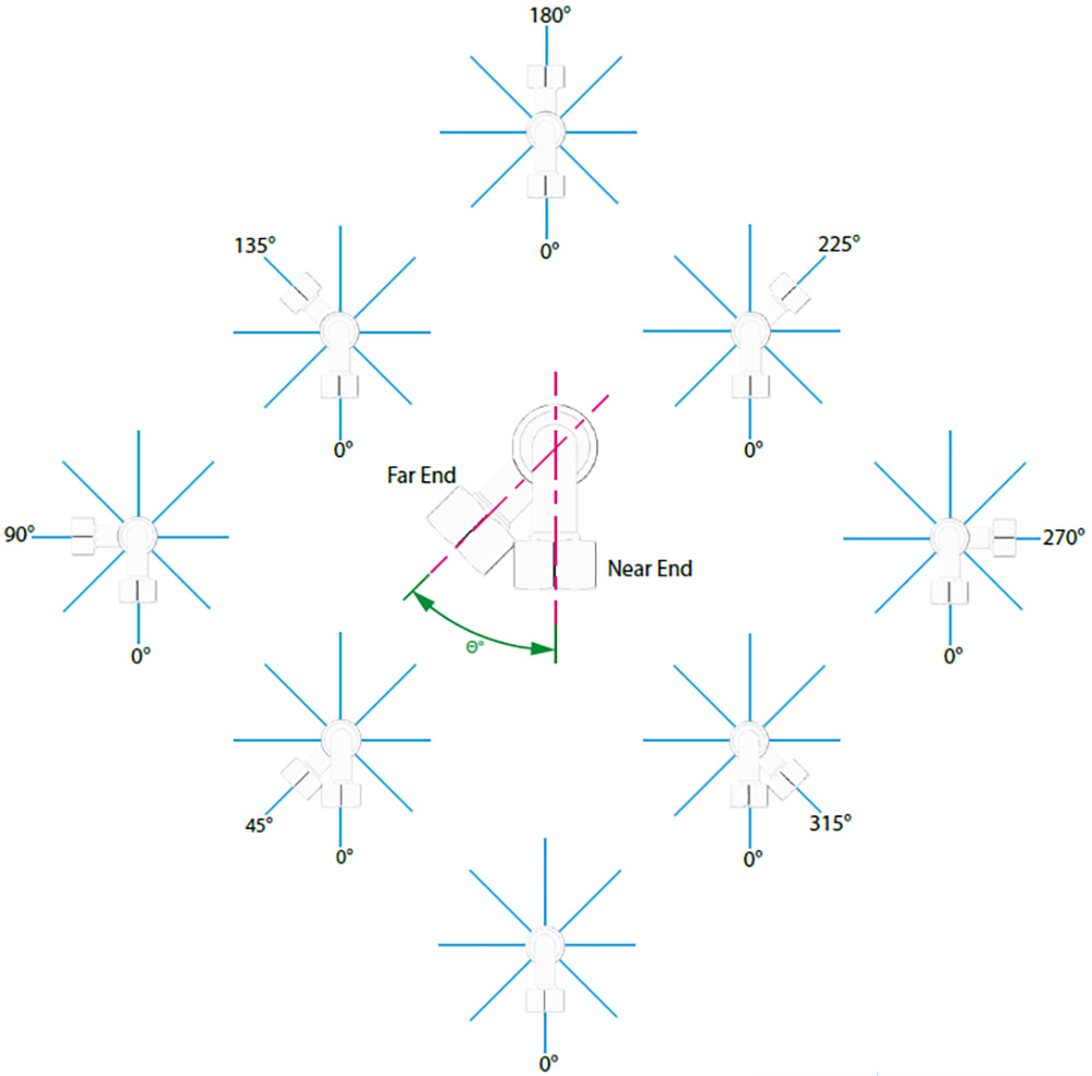
4.3 – Hose Clocking
When two elbow connections are specified for the same assembly it is usual for them to be angularly offset from one another as per the assembly drawing – referred to as “clocking”.
Unless otherwise specified in the assembly drawing, the angular tolerance according to international norms is:
- ±3° for overall assembly lengths (OAL) of up to 24”
- ±5° for overall assembly lengths (OAL) over 24” To identify the angle of a hose end, there are two different methods:
- Near End Reference Method (NER)
- Far End Reference Method (FER)
Note: It is important to verify the method of reference according to the assembly drawing.
The Far End Reference Method is the most commonly used:
- Hold the hose assembly as if you are looking into a telescope
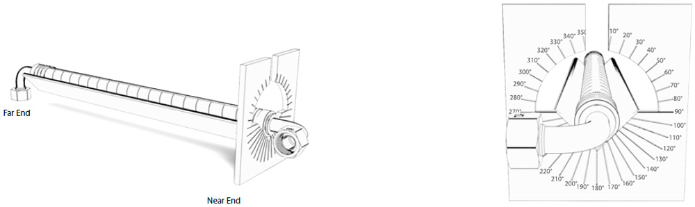
- Position the elbow fitting farthest from you to 6 o’clock position (straight down).
- Identify the position of the closest fitting, reading clockwise.
WARNING:
Once crimped, do not attempt to forcibly rotate or re-orientate the inserts. Doing so may damage the insert, ferrule or hose resulting in assembly failure.
Note: Incorrect elbow orientation may generate twist of the hose leading to premature failure.
5. Crimping
5.1 – Selecting the correct Die-Set
- In order to achieve a high-quality crimp, it is important that the correct crimping die-set is selected.
- The die-set used should be the one closest-to, and smaller, than the listed crimping diameter.
| Crimping Diameter | DIE N. | |
|---|---|---|
| mm | Inch | |
| 16.9 | 0.665 | 16 |
| 18.6 | 0.732 | 18 |
| 20.7 | 0.814 | 20 |
| 23.5 | 0.925 | 22 |
Note: For your convenience, and to minimise the risk of errors, Manuli Hydraulics’ published crimping data includes the recommended die-set for each hose and fitting-type combination.
IMPORTANT:
Always use the most recent crimping data published by Manuli Hydraulics.
Note: Each die-set has a permitted crimping range, which must be respected. The complete range of Manuli Hydraulics die-sets and their crimping ranges are detailed below.
| Nominal Die Size | Crimp Min (mm) | Crimp Max (mm) |
|---|---|---|
| 10 | 10.0 | 11.9 |
| 12 | 12.0 | 13.9 |
| 14 | 14.0 | 15.9 |
| 16 | 16.0 | 17.9 |
| 18 | 18.0 | 19.9 |
| 20 | 20.0 | 21.9 |
| 22 | 22.0 | 23.9 |
| 24 | 24.0 | 26.9 |
| 27 | 27.0 | 29.9 |
| 30 | 30.0 | 32.9 |
| 33 | 33.0 | 35.9 |
| 36 | 36.0 | 38.9 |
| Nominal Die Size | Crimp Min (mm) | Crimp Max (mm) |
|---|---|---|
| 39 | 39.0 | 41.9 |
| 42 | 42.0 | 44.9 |
| 45 | 45.0 | 47.9 |
| 48 | 48.0 | 50.9 |
| 51 | 51.0 | 53.9 |
| 54 | 54.0 | 56.9 |
| 57 | 57.0 | 62.9 |
| 63 | 63.0 | 65.9 |
| 66 | 66.0 | 69.9 |
| 70 | 70.0 | 72.9 |
| 73 | 73.0 | 75.9 |
Note: Users working with a reduced number of die-sets will not be able to produce satisfactory crimps on diameters outside of their die-set range.
WARNING:
Crimping with the wrong sized die-set can reduce the performance and quality of the hose assembly.
5.2 – Preliminary setup of Manuli Crimping Machines.
During the crimping setup, input the Nominal Crimping Diameter (DN) on the machine using the relevant set-stop mechanism.
Initial setup of mechanical and electro-mechanical visual set-stops
On machines with mechanical or electro-mechanical visual set-stops the formula for setting the Crimping Diameter Setting (DS) is:
(Nominal Crimping Diameter – Die-Set Value) x 100
DS = (DN – VDS) x 100
The above formula should produce an Actual Crimping Diameter (DA) which is close to the required value.
Example:
To achieve an Actual Crimping Diameter of 23.5mm using Die-Set 22:
DS = (23.5 – 22) x 100
DS =150
So, the mechanical / electro-mechanical visual set-stop should be set to a value of 150.
Note: The initial value of DS obtained from the formula above is intended as a starting point for correct setup.
Using the above formula does not guarantee an accurate Actual Crimping Diameter, and the validation and modification process (see section 10) should always be followed to ensure that the Actual Crimping Diameter is accurate.
Initial setup of electronic set-stops
On machines with SCE or SCS control, simply enter the Nominal Crimping Diameter
listed in the crimping data (eg. 23.5mm), and the automated system will calculate the correct Crimping Diameter Settings.
Note: The initial value calculated by the system is only intended as a starting point for correct setup.
The validation and modification process (see section 10) should always be followed to ensure that the Actual Crimping Diameter is accurate.
6. Validation & Modification of Crimping Settings
After the initial crimping operation, the crimped ferrule should be inspected according to the following procedures.
6.1 – Actual Crimping Diameter (DA) Check
- Take 4 measurements across the crimped ferrule diameter at 45° to one another as shown using vernier callipers or a micrometer gauge. The measurements should be taken from the middle section of the ferrule’s crimped length and from across the die landing areas NOT from across the raised ridges (see below).
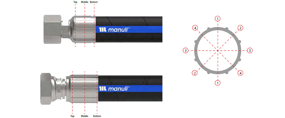
- Calculate the average crimping diameter using the four measurements taken.
- Verify that the calculated average of the measured values is within the acceptable tolerances of +0mm / -0.2mm of the Nominal Crimping Diameter.
Note: In order to have a robust crimping process, it is recommended that the Target Crimping Diameter be the value in the middle of the tolerance range – (DN -0.1mm). In this way it is easier to avoid out-of-tolerance crimps.
- If the calculated value is outside of the acceptable limits calculate the difference between this value and the required (Target Crimping Diameter) value. If this difference is greater than 0.1mm, mark the ferrule with an “X” and adjust the crimping machine settings by this value (either up or down depending on if the actual crimp is under- or over-sized).
Oversized ferrule diameter – Insufficient crimping
If the crimped ferrule diameter is too large, REDUCE the Crimping Diameter Setting (DS) by the calculated error value and re-crimp the same ferrule.
Example:
If the measured value is 23.8mm rather than 23.5mm then the error is +0.3mm.
To correct for this error the Crimping Diameter Setting (DS) should be reduced by 0.3mm.
In the case of a mechanical / electro-mechanical visual set-stop, the reduction would be 0.3 x 100 = 30.
In the case of an SCS or SCE controlled machine, the Correction Value (C) would be -0.3mm
Undersized ferrule diameter – Excessive crimping
If the crimped ferrule diameter is too small, INCREASE the crimping machine setting by the calculated error value.
Example:
If the measured value is 23.1mm rather than 23.5mm then the error is -0.4mm.
To correct for this error the Crimping Diameter Setting (DS) should be increased by 0.4mm.
In the case of a mechanical / electro-mechanical visual set-stop, the increase would be 0.4 x 100 = 40.
In the case of an SCS or SCE controlled machine, the Correction Value (C) would be +0.4mm
Then crimp the other end fitting of the assembly and then restart the validation procedure at Step 1.
Crimping correction
In this phase it is important to consider the crimp correction versus the preliminary set up for the following reasons:
- Reducing the Crimping Diameter Setting (DS) by “X” mm to compensate for the elastic rebound of the ferrule.
Normal values of correction are: “X” = 0.1mm to 0.4 mm (depending on hose size and type)
Note: On SCS controlled machines, the rebound value is already pre-set inside the uploaded chart.
In order to have a robust crimping process, it is recommended that the Target Crimping Diameter be the value in the middle of the tolerance range (Nominal Crimping Diameter -0.1mm). In this way it is easier to avoid out-of-tolerance crimps.
6.2 – Crimp Ovality check:
- Calculate the Crimp Ovality as the difference between the highest and lowest values that were measured at the start of section 10.1.
- If the Crimp Ovality exceeds 0.2mm, mark an “X” on the ferrule and inspect the crimping machine die head, springs and dies for damage or wear, replacing any defective parts.
6.3 – Crimp Taper check
- Take four diameter measurements (as described at the start of section 10.1) from both the top and bottom sections of the crimped ferrule.
- Calculate the average diameter of each position.
- Calculate the difference between the two average values – The result is the Crimp Taper value.
- Verify that the Crimp Taper value is within the following limits:
For hoses up to and including DN16 (5/8”), taper should not exceed 0.3mm For hoses from DN19 (3/4”) up to and including DN76 (3”), taper should not exceed 0.6mm
- If the calculated Crimp Taper value exceeds these limits, mark an “X” on the ferrule and inspect the crimping machine die-head, springs and dies for damage or wear, replacing any defective parts.
The crimping machine should now be correctly setup and calibrated ready for production.
IMPORTANT:
Scrap any assembly which has an “X” on the ferrule.
After completing the above setup process the crimping machine setting should not be altered.
Double striking of the ferrule is not allowed.
7. Crimping Operations
- MF2000 two-piece fittings and
- One-piece fittings
Position the entire length of the ferrule inside the dies in order to obtain a completely flat crimp.
Note: Leave some margin from the die set edge to include the possible elongation of the ferrule during crimping.
Double crimping of ferrules covering partial lengths in two or more strikes is not allowed.
- Crimp the next hose assembly end using the same crimp setting that was determined during the setup process.
- Take 4 measurements across the crimped ferrule diameter at 45° to one another as shown using vernier callipers or a micrometer gauge. The measurements should be taken from the middle section of the ferrule’s crimped length and from across the die landing areas NOT from across the raised ridges.
- Calculate the average crimping diameter using the four measurements taken.
- Verify that the calculated average of the measured values is within the acceptable tolerances of +0mm / -0.2mm of the Nominal Crimping Diameter.
- If the measured crimping diameter is outside of the allowable limits it indicates that the crimping machine is “out of control” and must be subjected to maintenance or repair as required.
- Repeat the above process for all hose assemblies of the same type.
It is not permitted to crimp Manuli hose assemblies to a value outside of the defined range (ie: Crimping chart value +0/-0.2) as specified in the latest version of the Manuli Hydraulics Crimping Data.
8. Proof Testing, Labelling & Certification
8.1 – Proof pressure testing
If internal proof pressure testing is required, it is recommended to follow the ISO 1402 or SAE J343 test procedures.
Proof testing should be carried out using compatible hydraulic fluid or water.
Do not use compressed gases.
If Individual Hose Assembly Test Documentation is required, each test certificate should bear a unique number for traceability. Test certificates should include the following information as required:
- Test certificate number
- Testing location and name
- Test procedure reference number
- Assembler’s name
- Fabrication number (if applicable)
- Hose assembly part-number and / or serial number(s)
- Hose assembly details including length, type of hose and size
- Hose assembly standard
- End fitting details that can identify types of ferrules and seals used
- Test date
- Confirmation that the hose assembly consisted of matched hose and hose ends
- Hose end information and check for correct matching of hose ends to hose
- Test pressure
- Pass / fail
- Signature of person inspecting
Note: For DNV Type Approval (or other TA such as ABS, LR, BV etc…) the Type Approval certificate number shall be listed on the test certificate.
8.2 – Labelling hose assemblies
When required, it is necessary to apply tagging on the hydraulic hose assemblies; tagging will make them:
- Identifiable
- Traceable
- Manageable
- Easier to be maintained.
The serial number and bar code on the tag is linked to:
- Product Bill of Materials
- Manufacturing information
- Test reports
- All other asset information
Tags are applied when hoses are assembled. Many tags types are available:
- Visually read types (Self-laminating label stickers, plastic tags, stainless steel tags)
- Radio Frequency types (RFID)
Note: Stainless steel may be required in the case with some Naval or DNV requirements.
All tags shall be resistant to weather, UV, corrosion and comply with country legislation.
8.3 – Certification of hose assemblies
A certificate of conformance should be supplied when requested. The certificate of conformance should have the following information, if applicable:
- Customer’s name, address, purchase order, contact details
- Specification, drawings, standards the assembly conforms to
- Supplier’s name, address, purchase order, contact details
- Supplier’s order number
- Description and quantity of supply
- Additional information as requested
- Supplier’s authorisation Signature
- Date of supply
9. Cleaning & Packaging
Hose assemblies should be supplied free from water, debris, metal shavings, dirt, or any other foreign material.
Hose bore shall have been cleaned carefully.
One suggested method is to clean with a foam projectile pellet being shot through the hose assembly in both directions.
Hose bore shall be inspected to ensure the cleaning pellet has exited the hose.
In case of specific requirements of hose assembly cleanliness, it is necessary to proceed with specific cleaning procedures of flushing and drying, following the detailed information of these processes (refer to equipment recommendations).
End connections should be sealed and capped to maintain cleanliness.
Hose assemblies should be packaged such that external abuse during shipping, handling and storage does not damage the hose or fittings.